Friday, February 17, 2012

Euclidean Subdivision

Playing around with Proposition I two mornings ago, I constructed a curious diagram.  On nice paper it looks like this:

Snell's Law
Euclidean SubD - Quad

The only thing given is finite segment AB.    There are two closed shapes: the square ABCD, and the shaded figure in the middle (mouse over).  Let's call the square the base geometry, and the curvy figure in the middle the subdivided geometry.  That's more or less what 3D programs call them.  The construction here is simple, but I'll list a few key details that might not be obvious:

 In Euclid's Proposition I , we draw two circles, and from these the square can be built.  For example,  AD is the radius of once circle, and tangent to the other.
   The sides of the subdivided figure are the points of equilateral triangles.
   To get the corners, I drew new circles around the four new points.
   The  point at the center and the segments connecting it are part of the new surface.  It thus has 9 points: 8 around the perimeter, and one at the center.

I have taken some liberties with Proposition  I.  For example, I have used the tangents of circles at points to construct the square.  I was doodling. 

The significance?
I think every 3D modeler recognizes this shape.   It is a smoothly subdivided surface.  Drop a Sub-D modifier onto your stack, and this is what happens to your model.  I have had subdivision on my mind for awhile, and I did not know where to start, so I started here.  I even made a plan for going through the Elements, and turning Propositions into algebra, vector equations, and algorithms.  But this is exactly what I wanted, and it only took the first Proposition!

I still need to make it an appealing and functional subdivision routine.  Several modifications should correct most of the problems:
1) As shown, none of the new points lie on the base geometry, which is too aggressive.  Next, I will split each edge at its midpoint, and leave these points on the base geometry.  Only the 'corners' will pull inside the original perimeter (or push out).  If the geometry is subdivided again, all points may lie off the original edges.
Splitting the edges at midpoints is also faster to compute.

2) The math does not need to be exact; it just has to look nice.  I used 30-60-90 triangles, so the distance to a new point is a term in √3.  I can choose friendlier numbers.  An even better solution is to build a template which gives the new topology like a stencil, tessellated across the whole mesh.

3) Triangles!  Arbitrary polygons can be divided into triangles. I need a subdivided triangle.  

Snell's Law
Fig. 2: Euclidean Sub-D: Tri

4) Topologically, all triangles can be seen as the same, all four-sided shapes the same....and so on.  I am not yet considering polygons with more than four sides, so Figures 1 and 2 cover all cases.

5)  Order of construction:
Edges first, then vertices.
The midpoint of any edge can be found, independent of the surrounding topology.  So I will begin there.
   i) Add midpoints to each edge.  For example, in the new version of Fig 2,  m1 will fall directly on the edge AB,  m2 on  BC,  and  m3  on AC.
  ii) When all edges of any polygon are split, add the center point.  This is easiest to see with Fig. 2.   If we complete the segments Am2Bm3Cm1,  they intersect at a common point in the center.
  A segment joining a vertex to the midpoint of the opposite side is called a median.  In a triangle, the three medians always intersect at a common point inside the triangle.  This point of intersection is the geometric center (or centroid).  So I will use it.
   iii) This leaves A',  B' and C'.   They may be connected to other polygons, or they may be free edges.  The same general rule can be applied to both cases.  Say C joins four polygons.  When all four of these polygons have a geometric center,  balance C' between these centers.
      The rule is then, when all adjacent polygons to a vertex have centers, balance the new vertex between them.
   Balance:    The geometric center of a polygon is its balance point.  Then the obvious approach is to balance A', B'.... the same way.  This is (I believe) a tensor.  Say all the lines connected to C are flexible.  Where does C fall if the tension on these lines is balanced?  Or relaxed?  This question results in a system of linear equations which are most easily handled as vectors.

6) The third dimension: I plan to ignore it.  A surface is is two dimensional.  For example, you can attach an image to any surface.  However much it curves in space, you can always paste (map) a flat image to it.  Every polygon either lies in a plane, or there is a plane that is closest to it.  Viewed in this plane, a polygon will appear to subdivide as if it were perfectly flat.  The amount any vertex moves out of this plane will be completely determined by the geometry of the model.  The more rapidly the base geometry is changing perpendicular (normal) to the plane, the less the subdivided surface will be able to follow it.  Sharp angles smooth to a more gradual change.

7) The distance function is two-dimensional.  The math is fine, but how will it look?  3D models are surfaces, but they represent 3-D shapes objects.  A 2D distance function might be too tight. Consider some distances:
    From the origin (zero)  to 1 on the number line:
           1 - 0     =  1  
    From the origin (0, 0) to the point (1, 1), in the x-y plane:
           √(12 + 12) =  √2.     (Pythagorean theorem)
     From the origin (0, 0, 0) to the point (1, 1, 1) in x-y-z space:
           (12 + 1+ 12) = √3.         (same)
 If AB in Fig. 1 has length of 2, then my unit subdivision length is √3.  I will keep this metric while developing the algorithm, and make the number under the root a variable.  I hope scaling the dimension of the subdivision length independently will make the algorithm both flexible and intuitive.  Scaling between "k=1.414" and "k= 1.732" on a linear slider may cover the same range of values as k = √2 , k = √3, but the relationship is unclear in the first case, and the scaling wrong.

I seek an adaptable subdivision method.  Once I have a working algorithm, I will revisit questions which I have glossed over.    #s 6 and 7  are such questions.  In general, "adaptable" implies greater sensitivity to rapid changes of direction in the base geometry (like corners).  Derivatives of higher order could be useful for a project involving assets designed from the ground up to be aggressively tessellated, and categorized by material type.
For example, how can a sub-D routine be tailored to hard surfaces?  And terrain? (...and types?)  Any spatial characteristics of the base mesh could be important factors.  One could also surely model using different subdivision templates throughout the mesh.  This would be labor-intensive for the artist, but it could also prove very efficient and intuitive, especially for hard surfaces, modeling for games.  Given by templates means a pool of scaled normal map files could potentially be used to speed normal map generation for complex surfaces, and to allow the low- and hi-poly meshes to be the same.  But that's just pretend for now;   this part of my project is not pressing.  It may be some time before I revisit subdivision and construct a basic algorithm.

Regardless, I think this provides sufficient generalization to tailor the algorithm to taste, and any problems which arise can be adjusted.  It's all made up of course, so maybe it'll be a disaster.  That's fine.  Now I have something to fix.


Make Your Own
I am happy to give the full construction of each diagram, and of my subdivision method when it is complete. It was more important to me to show how a subdivision routine can be constructed by anyone with a compass and straightedge.  The specific steps I have taken are personal preference.  I was playing a game with a compass.  Any way to break up a shape is a way to subdivide, and whatever people might want you to think, a bunch of special vocabulary is unnecessary.  It gets in the way.  If you follow that link, the authors will spend half a page describing a square with a diagonal drawn in it.  They will give it a special name.  Subdivision will appear mysterious, loaded with unforeseen complexities.*  It is not. 

Tell Me, or Ask A Question
If I have written about a problem, I have the time to go through every step.    Just ask.  I don't know what's missing from the explanation until someone tells me.  On the other hand, additional details make the broader picture harder to see.  There is a choice when writing about math: where to draw this line?
Ideally, the text should be both concise and complete.   This will take me quite some time to achieve, but that is my goal.  I tend to overcomplicate.  All suggestions about how ts can be more clearly presented are welcome.

I will add new diagrams in my next pass through subdivision.  This will provide additional clarity.

{* I had enough after a few pages.  I don't have the patience for this.}

Euclid's Elements

I began Euclid's Elements a few days ago.  Here is

Proposition I.  On a given finite straight line to construct an equilateral triangle.


Elements, Book I,  Proposition I


The construction is:
  (Given finite line AB)
  Draw the circle with center A and radius AB.
  Draw the circle with center B and radius AB.
  The two circles intersect at exactly two points.  Choose one of these points and call it C.
  Join the straight lines AC and BC.
  Then AC, AB are both radii of circle A :   AC = AB.
  And AB, BC are radii of circle B, and thus equal:  AB = BC.
  Hence AC = AB = BC.   The three sides are equal to one another, being the thing to be shown.


It's simple, but Euclid's method has garnered a lot of attention.  There is a great deal of nonsense said about Proposition I.  For example, consider the following passages from T.L. Heath:
"It is a commonplace that Euclid has no right to assume, without permissing some postulate, that the circles will meet in a point C.1  To supply what is wanted we must invoke the Principle of Continuity (see note thereon above, p. 235).2"
"Zeno's remark that the problem is not solved unless it is taken for granted that two straight lines cannot have a common segment has already been mentioned....  Thus, if AC, BC meet at F before reaching C,3 and have the part FC in common, the triangle obtained, namely FAB, will not be equilateral, but FA, FB will each be less than AB4.  But Post. 2 has already laid it down that two straight lines cannot have a common segment.5
"Proclus devotes considerable space to this part of Zeno's criticism....." 
What does the note on page 235 say?  It is astonishing!  Here is a bit:
"The use of actual construction as a method of proving the existence of figures having certain properties is one of the characteristics of the Elements.  Now constructions are effected by means of straight lines and circles drawn in accordance with Postulates 1−3; the essence of them is that such straight lines and circles determine by their intersection other points in addition to those given, and these points again are used to determine new lines, and so on.  This being so, the existence of such points of intersection must be postulated or proved in the same way as that of the lines which determine them.6  Yet there is no postulate of this character expressed in Euclid7 except Post. 5.  This postulate asserts that two straight lines meet if they satisfy a certain condition.  ....if the existence of the intersection were not granted, the solutions of problems in which the points of intersection of straight lines are used would not in general furnish the required proofs of the existence of the figures to be constructed. 8 
"But, equally with the intersections of straight lines, the intersections of circle with straight line, and of circle with circle, are used in constructions.  Hence, in addition to Postulate 5, we require postulates asserting the actual existence of points of intersection of circle with straight line and of circle with circle9.  In the very first proposition the vertex of the required equilateral triangle is determined as one of the intersections of two circles, and we need therefore to be assured that the circles will intersect.  Euclid seems to assume it as obvious,10 although it is not so; and he makes a similar assumption in I. 22."  
[The thirteen books of Euclid's Elements: Books I and II;  T.L. Heath and  J.L. Heiberg, Cambridge University Press, 1908; pp. 242, 234-5.  Available as a free Google ebook.  Footnotes mine; see below.]
That's not the end of it!  But, more to the point,


THE GRUMPY PART
this is all nonsense.  Pointwise, because these are arguments:
1.  Euclid does not assume it.  It is not in the postulates, definitions or the common notions.  Heath is upset because Euclid does not postulate the point in advance of the construction.  But no such postulate would be sufficient.   The question is, does the point, in fact exist?  It can only be given by demonstration, i.e. construction.

2. To supply what is wanted we must construct the point.

3.  !! They do not.
Are we playing pretendsies?
Suppose that instead of meeting at a point C, the lines intertwine, wrap one another in lengthening spirals.  Instead of meeting at a point C, the lines brood and tigthen, kink and curve against the paper.  The point C is not met.  There well be no more business of point C.  Suppose they push and crouch, the paper begins to flap about.  Suppose there is a pop of air as they free themselves, spring out of the page in snaking cylinders, work around the table and chair legs, hungry for rectilinear motion, dimension, line and curve.

4. There are two issues here.
First, this way of reasoning is called the fallacy of the irrelevant thesis: seeking to prove, perhaps successfully, an issue not in question.  If the point F existed, then the following problem would arise.   Indeed, let us grant this.  Then the question remains, does point F exist?  It does not.  It is an objection for a case which does not exist.  And what about the other cases which don't exist? What if AC, BC meet in a pony before arriving at C?  What if they follow the little piggy to market?

Second, a construction is an existence proof. All arguments which claim to truth rely upon facts independent of the argument itself; they admit revision.  Where something is given by construction, a valid construction is necessarily a valid counterexample.   Zeno clearly sees that revision is admissible, but does not seem to understand the structure.  All he has to do is construct the objection, and it will be valid. His constructions fail; they are pretend.
Euclid is not difficult to follow.  In the present case, all we need to do is build the point F .  Or a pony.  Or any of the infinite possible nonexistent cases which Euclid does not mention.

5. Postulate 2 is not necessary.  Zeno is ignoring Postulate 1: "To draw a straight line from any point to any point."  For example, a construction of Zeno's argument is presented here:
http://aleph0.clarku.edu/~djoyce/java/elements/bookI/propI1.html
Point C is right there.  He refuses to connect it, makes up a new point and connects that one instead. If Zeno does not agree to draw a straight line from one point to another, then he should object to Postulate I.  He is free to make any geometry he wants.  He seems to want Euclid's.  It is up to him to decide whether he accepts the postulates and definitions or not.

INTERMISSION
I'm arguing with a dead guy!
[pinocchio] I'm a real boy! [/pinocchio]

6. Hahahahahahahaha!  This is a good one!  "Sally's existence must be postulated or proved in the same way as that of the lines which determine her location."  !!   I want to try this sentence again, without going crazy in the middle.  "The existence of such points cannot be proved by argument; the points must in fact exist.  Hence, Euclid proceeds by construction of the points."

7.  Of course not.  What is strange to me about this sentence and what follows is that Heath reinterprets Postulate 5 every time he discusses it.  His interpretation and Euclid's definition imply one another; but Heath's version is less amenable to what he wants than the postulate itself.

8.  "Furnish...the proofs of the figures to be constructed"  ?       *!!*
If we insist on the argument,  the following cases are sufficient to demonstrate the error:
    -Suppose such proofs to exist, and the diagram also can be constructed.
           Then the diagram can be constructed.
     -Suppose such proofs not to exist, but diagram can be constructed.
           Then the diagram can be constructed.
       -Suppose proofs to exist which state the diagram cannot be constructed, and the diagram can nevertheless be constructed.
           Then the diagram can be constructed and the proofs are meaningless.
The proof is the construction itself.

9. No we do not.  Strike "postulates asserting".

10.  This is the heart of the matter.  Euclid does not assume this.  He seems clear that such assumptions are neither necessary nor sufficient.  If Heath refers to those properties which can be deduced directly from the Definitions, then of course Euclid assumes them.  But I do not think this is what Heath means.


I have overstated some of the points.  Take me to task!  There are additional complexities.  Where?  I am not dismissing continuity. I find  Euclid's Definitions sufficient to meet Heath's arguments, and more elegant than most modern theory on continuity.  But this is still not good enough.  In the end, the point must be drawn.  Else, the rest is sophistry.

Tuesday, February 14, 2012

Snell's Law, Part III

{<−− Part II}                                                          {Part IV −−>}
Snell's Law

Given the two angles, incident and transmitted, for a ray passing from one medium to another, to find the Index of Refraction by geometric construction.


For simplicity, I have again assumed the surface is horizontal in the plane.

Along any line parallel to the surface, the distance from the normal to the points of intersection with lines  ηand η2 are in the ratio η12 .

Now, picture the horizontal black line labeled IOR sliding up and down, causing the lines η1 and η2 to follow.  The line η2 will pull the vector i along with it, and by way of an auxiliary point of intersection of perpendiculars from i and t' to orthogonal radii of the circle, t' and t will move as well.  I say, as the bar is moved, the relationship between i and t will, for all positions, obey Snell's Law.  That is, the construction is complete, beginning with an arbitrary angle.

As an example, I have drawn the line IOR so that the distance from normal to η1 is the same as the radius of the circle, which is known exactly by construction.  There is no need to appeal to sines or cosines.  The ratio of η12  can then be worked out by segment subdivision with a compass until the desired accuracy is reached.
 In this (hypothetical) experiment, the IOR of the second medium is just slightly higher than 1.5x the first.  If the first is air, the IOR of the second is about 1.51  (η1 leans a little too far to the left, so η2 appears too close to it, and the subdivision marker).

This number should agree with trigonometric calculation (cheating).

If you mouse over the diagram, the red line is the continuation of θ2  from t'.  For small angles, x is an excellent approximation of sinx.  Working directly with angles, we might use this approximation, and thus the ratio  θ12, instead of sinθ1 / sinθ2.  In the present case, that would require measuring the ratio along the arc, which is more difficult than using the correct ratio.
We could also use this value by mistake. (Not that anyone has ever done that.*  Nosirree.)


{<−− Part II}                                                          {Part IV −−>}
_______________________
*Ptolemy.

Friday, February 10, 2012

Snell's Law, Part The Second

{<−− Part I }                                                       {Part III  −−>}
Part 1 gives Snell's Law as a vector equation.   I have only accounted for a case in two dimensions, with N vertical in the plane.  Before going further, a little cleanup is necessary.  The initial diagram should be altered to match the solution, and I need to determine my relationship to a certain ± sign.

Time for a brief word about
VECTORS
■  A vector V is a line segment directed from a point a to another point b, written
           V = (b - a).
We subtract: tip − tail.   This subtraction (b - a) gives a new point, which I will call  v.  V can still be written as a difference of two points:
           V = (v − 0)
where 0 is the zero vector, which has all components zero. 
Hopefully, that sounds silly; subtracting zero doesn't do anything.  That is exactly what I want:

■ Any directed line segment is equivalent to a vector with the same direction and magnitude (length) whose tail is situated at the origin.
Example: Given points a = (a1,  a2) and b = (b1, b2)
        

Generalization:
■ All vectors with the same direction and magnitude, wherever they lie in space, are equivalent. 

The Dot Product:  Given two vectors,  R = (r1, r2)  and   S = (s1, s2),
        
In three space, given  R= (r1, r2, r3)  and  S = (s1, s2, s3)
        

■ The result of the dot product is a regular-ass number (a scalar), not a vector.

■ The dot product of two normalized vectors gives the cosine of the angle between them.
Given  R = (cos α, sin α ),   S (cosβ  , sinβ )
        
This is enough to evaluate the solution offered in Part 1:
Vector Orientation
(Fig. 2)  - From Part 1 

Here again, the length of all vectors is 1.  The labeled points are then


The dashed line I' has the same direction and magnitude as I. Subtracting  tip − tail,
        

The two are the same.  But the angle between I' and N is  is (π − θ1), not θ1.  (Mouse over the image).
 Hence the angle between I and N  should also be (π  θ1).  Is it?
        

Yes.   I want   I•N   to give cosθ1, so I will change its direction:
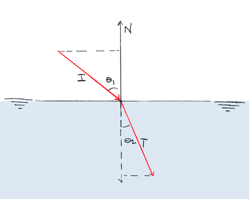
(Fig. 3)  Corrected, N-Up

This is the correct diagram for the result in Part 1.  This is the definition of I that I used, and the formula should already be correct.

DEFAULT ORIENTATION
There is a trap waiting for me, and it's time to fall in.  The ± need to go.

What happens if the light comes from the other side?  In Fig. 3, what if I is on the right?  The mirrors of I and T share the same cosine.  The dot product does not distinguish between +θ and  −θ.   There are several ways to resolve this, which I am putting off to part 5.

I have chosen to set the default orientation in advance.  I've decided to cheat.  The computation of snell's law will happen in object space.  This is permitted by  a series of simplifying assumptions for real-time, which allow me to compute a reference plane once for the entire object:
  1.  The surface in question is a sheet.
    It has a top side and a bottom side.  It is not necessarily flat and, for caustics, probably should not be.  Picutre a lake.
  2. There is an up-direction.
     For a lake, on Earth, this is defined by gravity.  Air above, lake below.
  3.   I will call the unit vector in this direction the reference normal, or the facing normal.  In local coordinate space I will  label it Z.
  4. The reference normal can be in any direction in the game world.
    The lake can be upside down.  What matters is that the direction be defined.  Medium 1 will always lie on the positive side of the surface.  Specifically,
  5. From the global coordinate space, the quadrant in which the light source lies, relative to the surface is already determined.
Example:
Pick any of the diagrams.  Place a boat on the surface of the water.   Now add waves.  The waves can pass freely through the diagram.  We could make a boat stability simulation: genetic algorithm builds boat, boat drops in water, waves pass through and rock the boat about.  A good boat does not sink.
In all of these cases, our 2D view stays put.  The surface normal changes as the waves pass through, but the air is always above, the water below.

To look at the boat from the side, we can rotate around it.  Of course, we leave the sky up, and the earth down.  The z-axis stays put.  This is the heart of my simplifying assumption.  I *think* it is why liquid surfaces are usually sheet meshes in a game engine, and not enclosed volumes.

I will not resolve the sign of θ for each ray. I will compute a Very Large Number of rays, rotate the surface, perform A Lot More, and so on.  I also believe this assumption will generalize further: I want to compute (fake) global lighting and caustics in rings at each point, using a MuchSmallerNumber of indiviual light paths.


FORMULA, N-UP:
Back to the diagram.  In this case,  the L is some positive angle less than 90 degrees from N.  I take the positive square root for sinθ1; the first component of I is −sinθ1, the first component of T  is (positive) sinθ2, as shown in the diagrams.  And thus the formula:

This was actually the first formula I came up with.  Since I had peeked at the solution in the nVidia paper, I knew they had a ± I did not, and I backed up to recreate the difficulty which leads to its adoption.  I found it very instructive.  I had played around with the cross product and determinant, but still did not have a clear picture of how to resolve sign in a consistent manner, at different places in the transform.

{THIS IS ALL PRETEND}
I am making all of this up. I could be wrong about anything!  I could also be a seven-legged, scabby froodle.  But I'm a bit more worried about being
 Super
    Wrong.
Let me know!
{<−− Part I }                                                                {Part III  −−>
{CodeCogs does LaTeX equations for free.  Thanks, guys}

Thursday, February 9, 2012

Snell's Law: Part The First

When light crosses from one medium to another of a different density, its speed and wavelength change.  Where it strikes the new surface at an angle, the transmitted wave is refracted, that is, the light changes direction.

Light which intersects a surface is incident.  The light which passes through the surface is transmitted.  The line perpendicular to a surface at a point p is normal to the surface at that point.   According to Snell's Law, we can assign to each medium a constant value η (eta), called its index of refraction (IOR), which satisfies the following relationship:
(1)                                                   η1 sin θ1 = η2 sin θ
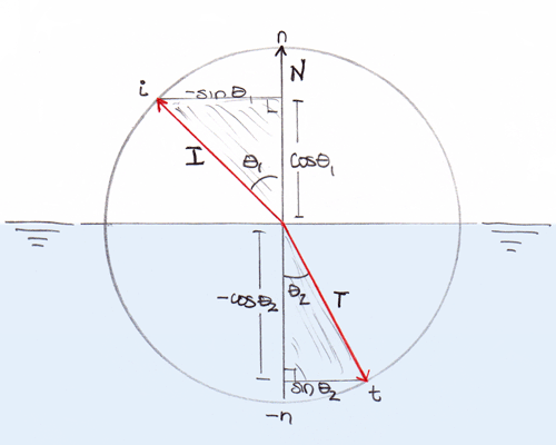
where η1 and  η2 are the indices of refreaction of the first and second media, respectively, θ1 is the angle between the incident ray and the surface normal, and θ2 is the angle between the transmitted ray and the normal.
Snell's Law
Fig. 1

In Fig. 1, incident ray I strikes a new medium, and the transmitted ray T is refracted.  Each is shown as the hypotenuse of a triangle.  If both  and are drawn with a length of 1 (if they lie on a unit circle), then the opposite sides of the triangles will have lengths sin θ1 and sin θ2   (mouse over the image).  According to Snell's law, the relationship between these two lengths and their corresponding angles is completely determined by the constant ratio η1/ η2:
 
I will explore this equation in depth over several blog entries.

Assumptions
{  Edit: this section has been reworked.  I seek clarity in method and presentation.  If a question appeared here and vanished, I will visit it at a later point.  If you think I should retain, and strike, prior text  ( like so ) let me know.   Thanks to Peter Schaefer for assistance with assumption ii. }

i) The surface normal is vertical in the reference plane.
ii) The transmitted light will lie in the same plane as the incident ray and the surface normal.  In the diagram, there is a single transmitted ray.

The first assumption is made for simplicity.  For rigid geometric objects, relationships between angles are invariant under translation and rotation.  For example, if you print out Fig.1 and set it in front of you on the table, spinning the page around will not change the measure of any of the angles.  This problem is easier to solve for N = (0, 1) than for arbitrary N.

I assume (ii) as part of the definition of Snell's Law.  That is, it is a physical result. 
The difficulty is this.  As mentioned in the nVidia paper, equation (1) alone does not appear to restrict T to the same plane as  I  and N.  For, what is to prevent you from cheerily rotating T around the dotted line and forming a cone?  Nothing.  The interior angle remains θ2 all the way 'round. Thus, by the Who's Going to Stop Me Theorem T need not lie in the given plane.  This may be done independently of a cheerful disposition.
However, I have given the incident ray and surface normal as vectors.  Together, I and N give the plane in which T will lie.  That is the point of the diagram.  I will state the restriction mathematically and account for it later, when I move the result to 3 dimensional space.

Onward.


For computation on graphics hadware, it is desirable to express Snell's Law in vector notation.   Thus,

Call the incident vector  I, the normal to surface N, and the transmission vector T. Assume I, T and N are normalized (each has a length of 1), and all lie in the same plane.  Then,
GIVEN: η1, η2, the indicies of refraction of the two media,
LET:
(2)  N = (0, 1)
      I = (–sinθ1, cosθ1)
     T = (sinθ2, –cosθ2)

The dot product of two normalized vectors gives the cosine of the angle between them.  Hence,
(3)   IN = cosθ1

I will also need the following trigonometric identity:


The Problem: Give T as a vector equation in η1, η2, N, and I.
This requires two steps , which may be done in any order.

I. Calculate T for any given η1, η2, N and I.
If I rewrite sinθ1,  sinθ2  and  cosθ2  in terms of  cosθ1 = I N,  I can give each component of T as a vector equation.

sinθ1 :  By (3) and (4), sinθ1 becomes

sinθ2 :  By Snell's Law (1),  sinθ2 = (η1 2)sinθ1   and by (4),

cosθ2 :  Substituting this value of sinθ2  into (4):


We can now give T = (sinθ2, -cosθ2):

This is correct, but in the vector T = (t1, t2), t1 and t2 have been solved separately.  I seek slightly more than this; I want to solve both simultaneously.  Hence,

II. Give T as the sum of two vectors.
Specifically, I want to write T as a linear combination of the two given vectors, N and I:
(9)        T      =     αI     +    βN ,         α, β constant:
       

This is another way of writing a pair of equations, with unknowns α and β:
(10)       sinθ2 = –α sinθ1
           –cosθ2 =  α cosθ1β
α: The first equation gives α directly.   α =  –(sinθ2/sinθ1)   which, by (1), is
(11)       α = –η12
β: Substituting this value of α into the second equation,
(12)       β = (η1/ η2)cosθ1 − cosθ2

Now the two steps can be merged.  Using the values for cosθ1 and cosθ2 in (3) and (7),

Substituting the values for α and β in (11) and (13) into T = αI + βN  gives  the desired relation:
                   

I have not derived a new formula, nor have I developed one of my own.  The above equation is an exact restatement of Snell's Law, in vector notation.

{Thanks to CodeCogs for their free LaTeX equation editor and image generation.}

Numerical Methods

Sometimes, while I am working, I will run across sentences like this:
...which can be computed according to the following formula given by SoAndSo, SomeDate:  {SomeFormula}.

I will stop reading, close the paper, and work out the relationship for myself.

There are several reasons.

The first is about me.  I doubt solutions until I can demonstrate them to myself.  I do not value memorization at the expense of comprehension.
We may rearrange a problem however we wish using the rules of algebra and geometry.  If mathematics is a language, it has only a few words.  The rest is concision and clarity.  I think the student who can manipulate 12th century Persian Algebra and weild a protractor, compass and straightedge, and know what she is up to, may gain ground as quickly as she like on University coursework in computer science and programming.

I seek to describe and solve problems in acoustics, wave propagation, and signal processing.  The state of sound design tools is poor, and their advancement is hindered by errors of logic and observation, accepted as common knowledge and understanding.  To identify, describe, and solve these problems, it is sufficient to construct mathematical descriptions of sound, and account for the physical properties in a consistent way.  The errors are basic.  They can be demonstrated with a walk down the street; walking around a streetlight; listening to a train.  To make the properties of waves more intuitive and accessible --and to insure that they are correctly accounted for-- I have constructed a series of analogies to light: construction of an image, its properties, and the mechanics of wave propagation.  My solutions will follow directly from known mathematical results, and observation of the physical world.  I work out each problem from scratch. I teach myself the necessary math, mostly out of old Dover press paperbacks.

Patents and Mathematics
The second reason is about mathematics.  All mathematical results follow inescapably from the definitions and rules of manipulation.  (Which is not to say easy.)  A valid result is one which can [and will] be obtained independently by anyone [and everyone].  The proof is demonstration.  The bracketed words are the heart of the matter.

Not everyone is clear about this.  That is a problem, and each person has to decide how to handle it.   I choose not to be slowed down.  I do not have time to pretend that a person can own math.  I sequester myself; I will not copy another person's mind. I have always worked this way, and I love it.  The history of mathematics is free to use, and any results I derive from it are equally free.  So therein I will work.

I am not overly fond of Modern Abstract Mathematics.  Proponents often confuse themselves with the tools they advocate, and say what anyone can understand  in a way that only a few people can.  The proofs usually run backward, never identifying the structure of the problem.  So I practice going backward in time, to obtain the answer.  Each time I go back, what I find is worth the trip.

There is more at stake than money, time, or the enjoyment of mathematics.  Math belongs to no one.  We are ethically responsible to make it accessible.  We also have a rational responsibility.  Mathematics is a logically elaborated structure; within it appeal to authority is baseless.  Any declaration of ownership can be shown to be invalid.
The last two sentences are exact.  There is no other ground to take.

It's alright.  I won't use or examine methods which claim to ownership.  If you Own algorithms, I won't read your paper; it can sit quiet on the shelf. I do not want to know anything about what you are up to.  If we stumble into each other, there will be no question.   All I will need is a chalkboard.

Onward.

Example, With Train
 Recently, I was reading a paper on efficient computation of caustics.  Here is where I stopped:
"Let's forget about reflection for a moment and see how transmitted photons are refracted according to Snell's Law, which states that:  η1 sin θ1 = η2 sin θ2,   otherwise written as:
IOR = η1/η 2 = sin θ2/sinθ1
In the preceding equations, η1 and η2 are the indices of refraction for the respective materials, and θ1 and θ2 are the incident and refraction angles, as shown in Figure 2-2. The index of refraction, IOR, can then simply be written as the ratio of the sines of the angles of the incident and refracted rays.
Snell's Law is not easy to code with this formulation, because it only imposes one restriction, making the computation of the refracted ray nontrivial. Assuming that the incident, transmitted, and surface normal rays are co-planar, a variety of coder-friendly formulas can be used, such as the one in Foley et al. 1996: [....]"
[from, http://http.developer.nvidia.com/GPUGems/gpugems_ch02.html . Italics mine.  Diagram omited.]

I have left out the next line.  I glanced at it, but it was unfamiliar so I stopped, closed the paper, and began working from scratch.  The citation was just the icing.

   This is from a book called GPUGems which is available for free on nVidia's website. This is a great idea, and I hope more companies catch on.  I work alone on a limited budget and the GPUGems series, and nVidia in general, distinguish themselves for free numerical methods, heaped with examples and explanations.  When I am employed, one of my first treats to myself will be to purchase the whole series.
It makes me think selling numerical methods is easy, as long as you don't patent them.  You print them, and then you can sell them.  People will buy them so they can use them.  There's a word for this kind of cooperative-competitive market model, but I just can't remember what it is....


In this case, I do not think there is a problem.  Citation is essential to research and the propagation of knowledge.  I can investigate further if I want, and the author is a good professional  neighbor to boot.  But why don't we solve the problem anyway?  How do people resist?

Problem:  Assuming that the incident, transmitted, and surface normal rays are co-planar, derive a [varitey of] coder-friendly formula[s] for the direction of the transmitted ray.
___________
Update:  I am deeply indebted to Professor Herbert Gross for his clear and concise language.
  Inescapable at last supplies what is wanting in the troublesome expression, self-evident.
Professor Gross' video lectures at MIT's Open Course Ware can be found here.